Development
Contents
Specifications
The task consists to build a system in the shape of a soda can wich will be launched at about 1 km altitude.
The requirements are:
- All the components of the CanSat must fit inside a standard can of 115 mm height and 66 mm diameter, with the exception of the parachute and possible antennas on the top or bottom of the can (not on the sides)
- The antennas, transducers and other elements of the CanSat cannot extend beyond the can’s diameter until it has left the launch vehicle.
- The mass of the CanSat must be between 300 and 350 grams. CanSats that are lighter must take additional ballast with them to reach the 300 grams minimum mass limit required.
- Explosives, detonators, pyrotechnics, and inflammable or dangerous materials are strictly forbidden. All materials used must be safe for the personnel, the equipment, and the environment.
- The CanSat must be powered by a battery and/or solar panels. It must be possible for the systems to be switched on for 4 continuous hours.
- The battery must be easily accessible in case it has to be replaced or recharged.
- The CanSat must have an easily accessible master power switch.
- Inclusion of a retrieval system (beeper, radio beacon, GPS, etc.) is recommended.
- The CanSat should have a recovery system, such as a parachute, capable of being reused after launch. It is recommended to use bright coloured fabric, which will facilitate recovery of the CanSat after landing.
- The parachute connection must be able to withstand up to 1000 N of force. The strength of the parachute must be tested to ensure that the system will operate nominally.
- For recovery reasons, a maximum flight time of 120 seconds is recommended. If attempting a directed landing, then a maximum of 170 seconds flight time is recommended.
- A descent rate between 8 and 11 m/s is recommended for recovery reasons. In case of a directed landing, a lower descent rate of 6 m/s is recommended.
Development
Tasks and groups
Additionally to the system engineering, the work comprises the development of:
- the enclosure
- the data acquisition electronics
- the power supply
- the parachute
- the ground operations
The work has to be distributed to responsibles according to the tasks the tasks, including the systems engineer.
Technology Readiness Levels
Levels
ESA defines the following Technology Readiness Level (TRL) sequence:
| TRL | Level Description | Demonstrator |
|---|---|---|
| 1 | Basic principles observed and reported | |
| 2 | Technology concept and/or application formulated | |
| 3 | Analytical and experimental critical function and/or characteristic proof-of-concept | Breadboard model |
| 4 | Component and/or breadboard functional verification in laboratory environment | Elegant breadboard |
| 5 | Component and/or breadboard critical function verification in relevant environment | Engineering model |
| 6 | Model demonstrating the critical functions of the element in a relevant environment | Qualification model |
| 7 | Model demonstrating the element performance for the operational environment | Flight model |
| 8 | Actual system completed and accepted for flight ("flight qualified") | |
| 9 | Actual system "flight proven" through successful mission operations |
Technology application
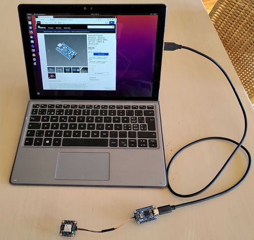
The different components can be individually connected to a PC via an USB to I2c (or to SPI) bridge and tested in order to check how they work.
Breadboard model
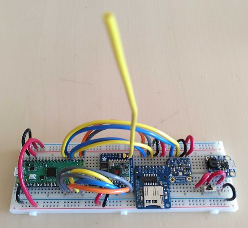
The breadboard model is functionally and electrically representative of flight hardware. It is used to validate a new or critical feature of the design.
The following picture shows a breadboard which allows to test the controller together with different breakout boards. This can be used to test the integration of the system components and to start coding the flight software.
The following picture shows the main controller together with a chain of I2C devices. This can be used for making outdoor measurements.
Elegant breadboard
The elegant breadboard is built using commercial grade components and a configuration close to that of the flight model. It is not made out of physically separated units interconnected by cables and wires but a fully integrated unit with interfaces representative of the flight model.
Engineering model
The engineering model is fully representative of the flight model except that a lower standard of electrical components may be used.
Qualification model
The qualification model is built to the full flight standard. It is used for qualification testing.

